Here’s a quick guide on exporting a board from Altium Designer 14 to be made by OSHPark.
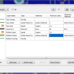
1. Go to Design -> Layer Stack Manager
2. Set your stackup to be this:
This information was derived from this FAQ.
3. Go to Project -> Compile PCB Project. Fix any errors that could cause a problem.
4. Go to File -> Fabrication Outputs -> Gerber Files
5. Under ‘General’, set the units to be ‘Inches’ and the Format to be ‘2:4’
6. Under ‘Layers’, select the following layers:
- Top Overlay
- Top Paste
- Top Solder
- Top Layer
- Bottom Layer
- Bottom Solder
- Bottom Paste
- Bottom Overlay
- Mechanical 15(assuming that you have drawn your board outline on mechanical 15)
Now export, save as <projectname>.cam
7. Go to File -> Fabrication Outputs -> NC Drill. Use the following settings:
- Units: Inches
- Format: 2:4
- Leading/Trailing Zeros: Suprress trailing zeros
- Coordinate Positions: Reference to relative origin
- Other: Optimize change location commands
Save as <projectname>-NCDRILL.cam
8. With the NCDRILL.cam file selected, go to File->Export->SaveDrill. Set the extension to be .xln
9. Go to your project folder, there should now be a sub-folder called ‘Project Outputs for <Project Name>’. Grab the following files:
- *.xln
- *.GBL
- *.GBO
- *.GBP
- *.GBS
- *.GKO(re-name the .GM15 file to be .GKO)
- *.GTL
- *.GTO
- *.GTP
- *.GTS
Put these all into a .zip folder.
10. Upload the .zip folder to OSH Park.
11. Have fun!

Leave a Reply